Throughout this guide, left is designated as the driver's side of the vehicle, and right as the passenger's side of the vehicle.
Section III: Wiring Installation
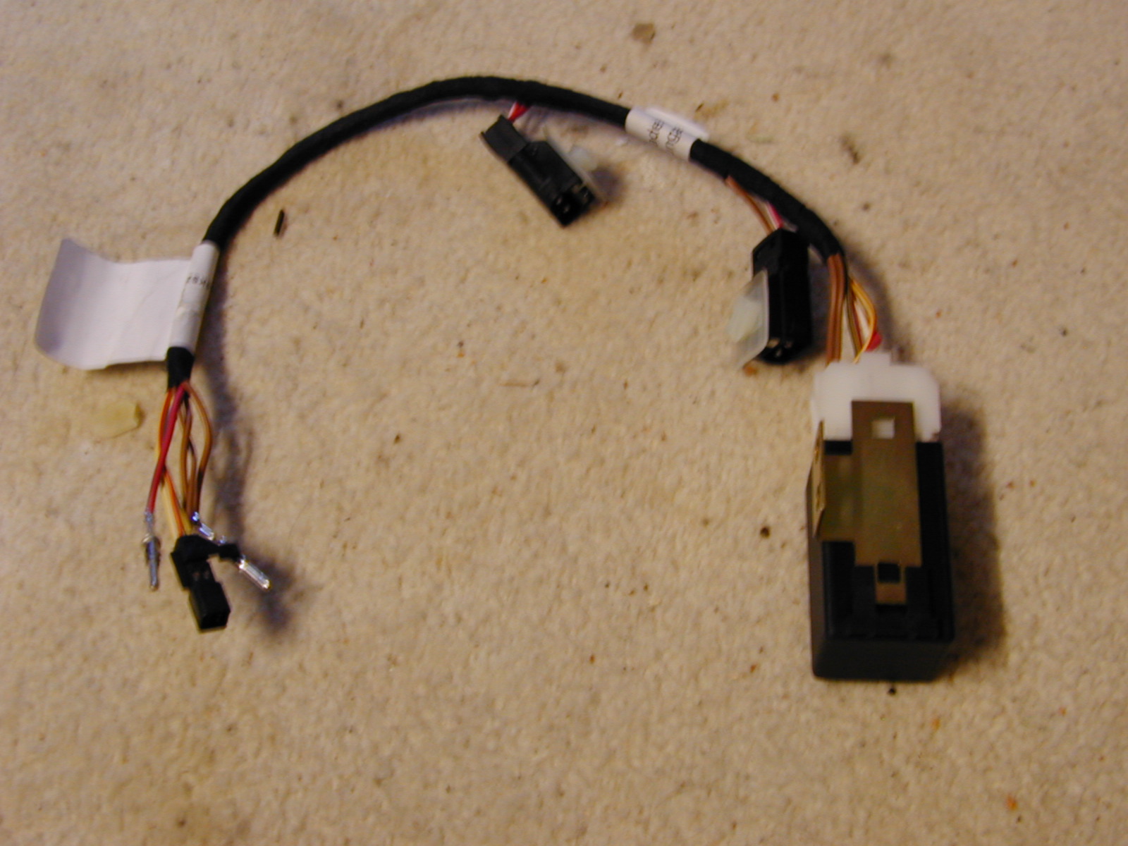
Building the Harness
I've split part of the harness into subgroups for two reasons. First, the runs terminate in different locations and thus have different lengths, which make it more tedious to put into a single bundle. Secondly, having subgroups also make it easier to replace or repair individual runs if necessary rather than taking out everything. There are two subgroups, and everything else is single wire runs. For each of the subgroups you'll want to take the three individual wires and wrap them with commercially available pressure sensitive tape to make a small bundle.
- Driver seat to driver console switch (3-wire bundle)
- Passenger seat to passenger console switch (3-wire bundle)
I have already provided measurements for the different wires and bundles. If you wish to take different routes or do your own measuring, I recommend laying string in the locations that you wish to run the wire. Run the string in exactly the same location(s) as the wires will be run. For example, run a string from the passenger seat to the fuse box, then remove it from the car and measure it. In either case, you should give yourself some extra length on the wires, so that they stick out of it several feet at the ends. This excess will allow you to cut each wire exactly to length once it is in the car, and you will put the connectors on then.
When buying wire, the cheapest route is to buy a large spool of each applicable gauge to cover all of the runs. The disadvantage of doing it this is that you will end up doing the whole harness in just a single color. While I didn't go to the extent of paying for on-wire labeling and striping, I did buy wire in several different colors in order to make it easier to locate and troubleshoot. In addition, I placed a label at each end of every single wire that lists the original Porsche color codes from the wiring diagram as well as the destination. This makes it easy to cross reference the wiring diagrams at a later time. For example, a label might read: "YE/WT to Passenger Seat". I used file folder labels. They are cheap, come in various colors, self adhesive, and readily available. It's not quite as easy as just looking for the yellow wire with the white stripe, but it's close and more economical.
Running the Wiring
This diagram gives you an idea where each of the runs will be located throughout the car. Note that the two yellow subgroups are each made up of a three-wire bundle.
 Note: Porsche lists their wire gauges in mm2 (metric). U.S. manufacturers go by American Wire Gauge (AWG). Provided above is the wiring diagram listing in mm2, with the nearest AWG equivalent (rounded up for safety reasons).
| Passenger Seat to Passenger Console Switch |
|---|
| | |
| No. | Procedure | Instructions |
|---|
| 1 | Seat to door sill | Starting at the cutout in the carpet under the passenger seat you'll follow where the factory wiring is laid by running it under the carpet towards the door sill. |
| 2 | Along door sill | Insert the cable into the rear end of the passenger door sill, and push it forward until you can reach it at the other end. Your wire puller will be helpful here. |
| 3 | Kick panel | It will be necessary to pull the kick panel carpeting back a little to follow the main harness from the sill up towards the dash. |
| 4 | Under dash | Run your wire under the dash until you reach the center console. Thread your wire through the console and pull it out the center opening of the gold colored bracket. |
| 5 | Around airbag sensor | Route around the airbag sensor unit. |
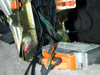
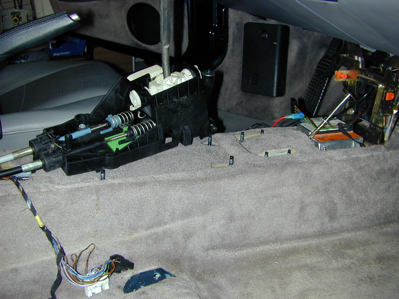
| 6 | Under gear shift | Run your wire under the carpet, between the exposed mounting bolts, and have it exit behind the gear shift mechanism where your power window wiring resides. Notice wire puller in the photo. |
 Tip: You may want to start your Passenger Seat to Fuse run at the same time so that you only make one pass through the door sill. Tip: You may want to start your Passenger Seat to Fuse run at the same time so that you only make one pass through the door sill. |
| Driver Seat to Driver Console Switch |
|---|
| | |
| No. | Procedure | Instructions |
|---|
| 1 | Seat to door sill | Starting at the cutout in the carpet under the driver seat you'll follow where the factory wiring is laid by runnning it under the carpet towards the door sill. |
| 2 | Along door sill | Insert the cable into the rear end of the passenger door sill, and push it forward until you can reach it at the other end. Your wire puller will be helpful here. |
| 3 | Follow main harness | Follow the main harness from the sill up towards the dash. |
| 4 | Under dash | Run your wire under the dash until you reach the center console.Thread your wire through the console and pull it out the center opening of the gold colored bracket. |
| 5 | Around airbag sensor | Route around the airbag sensor unit. |
| 6 | Under gear shift | Run your wire under the carpet, between the exposed mounting bolts, and have it exit behind the gear shift mechanism where your power window wiring resides. Notice wire puller in the photo. |
| Tip: You may want to start your Driver Seat to Fuse run at the same time so that you only make one pass through the door sill. |
| Passenger Seat to Fuse Panel |
|---|
| | |
| No. | Procedure | Instructions |
|---|
| 1 | Seat to door sill | You'll begin by following the same path as you did with the Passenger Seat to Console run. Starting at the cutout in the carpet under the passenger seat you'll follow where the factory wiring is laid by running it under the carpet towards the door sill. |
| 2 | Along door sill | Insert the cable into the rear end of the passenger door sill, and push it forward until you can reach it at the other end. Your wire puller will be helpful here. |
| 3 | Kick panel | It will be necessary to pull the kick panel carpeting back a little to follow the main harness from the sill up towards the dash. |
| 4 | Under dash | Run your wire under the dash across to the fuse panel located in the driver side footwell. |
| Driver Seat to Fuse Panel |
|---|
| | |
| No. | Procedure | Instructions |
|---|
| 1 | Seat to door sill | You'll begin by following the same path as you did with the Driver Seat to Console run. Starting at the cutout in the carpet under the driver seat you'll follow where the factory wiring is laid by running it under the carpet towards the door sill. |
| 2 | Along door sill | Insert the cable into the rear end of the passenger door sill, and push it forward until you can reach it at the other end. Your wire puller will be helpful here. |
| 3 | Follow main harness | Follow the main harness from the sill up towards the fuse panel. |
| Driver Console Switch to Ground Point |
|---|
| | |
| No. | Procedure | Instructions |
|---|
| 1 | Under gear shift | Start where your power window wiring resides and run your wire under the carpet, between the exposed mounting bolts, and have it exit in front of the gear shift mechanism . Notice wire puller in the photo. |
| 2 | Around airbag sensor | Route around the airbag sensor unit. |
Note: The factory Ground Point 4 (GP4) is extremely difficult to find, much less connect to. I opted to ground to the gold colored metal bracket.
Tip: You may want to start your Driver Switch to Relay run at the same time so that you can reduce the number of passes you make under carpet. |
| Driver Console Switch to Relay |
|---|
| | |
| No. | Procedure | Instructions |
|---|
| 1 | Under gear shift | Start where your power window wiring resides and run your wire under the carpet, between the exposed mounting bolts, and have it exit in front of the gear shift mechanism . Notice wire puller in the photo. |
| 2 | Around airbag sensor | Route around the airbag sensor unit and push your wire through the center opening of the gold colored bracket. |
| 3 | Under dash | Thread your wire through the console and run it under the driver side dash across to the relay panel. |
Test Wires
Before proceeding, it's a good idea to test all of your wires. This may seem tedious, but it's much easier to find and correct problems before you attach the wires to anything. No matter how careful you think you've been, there's always the possiblity of error. At best, you've mislabeled a wire. At worst, a wire has been damaged during the run.
You'll need to do a continuity test with a self-powered test lamp or an ohmmeter to tell if the two wire ends are connected to each other and uninterrupted. Be sure to make sure your test tool works before troubleshooting the wire.
Making Connections
Tip: When making your connections you should have these basic steps:
- Cut wires to length, making sure you leave enough to follow existing wiring runs
- Strip wire ends to a length of 10mm
- Push on heat shrink tubing
- Crimp and/or solder your connection
- Shrink heat-shrink tubing over connection area with a hot-air gun (lighter/soldering iron)
- Test continuity with connectors on, before inserting into housings
| Ground Point |
|---|
 | | |
| No. | Procedure | Instructions |
|---|
| 1 | Crimp on connector | Crimp on a generic spade terminal connector to your BR wire running from the Driver Console Switch. |
| 2 | Loosen bolt | Loosen the existing bolt. |
| 3 | Insert connector | Slide your connector underneath |
| 4 | Tighten bolt | Fasten connector by tightening bolt. |
| Note: The factory Ground Point 4 (GP4) is extremely difficult to find, much less connect to. I used the gold colored metal bracket near the front of the console as an alternate. |
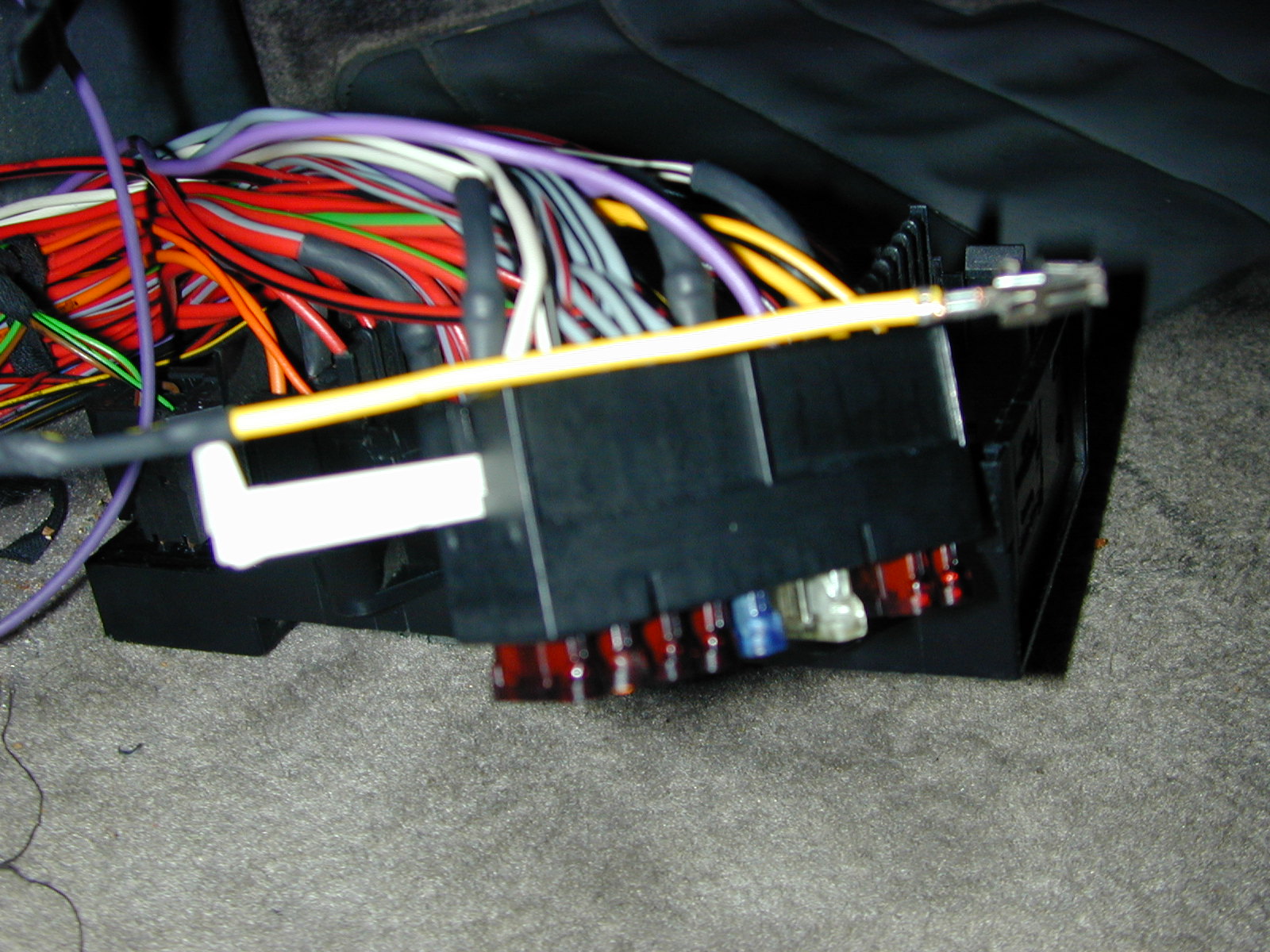
| Fuse Panel |
|---|
 | | |
| No. | Procedure | Instructions |
|---|
| 1 | Join wires | Twist together the RE/VI wires from the Passenger and Driver Seats. Make sure that you have enough slack in your wires to follow the same path as the existing fuse wiring. |
| 2 | Solder to connector | The Audi 000-979-227 Electrical wire/Connector should be a yellow wire with connectors on both ends. Cut the Audi wire in half and solder your RE/VI wires to one of the Audi pieces. Your two RE/VI wires should now end with a single female blade to fuse connector. |
| 3 | Access SI A6 | The connector will go into the top opening of -SI A6- in the fuse panel. When viewed from the front, this is the top row, sixth one from the left. You access this section by lifting the side clips and pulling it out of the main housing. Then slide out the gray retaining piece. |
| 4 | Insert connector | Insert your connector into the top portion of -SI A6-. Keep in mind the orientation of the connector, and notice that the bottom connector for this fuse is already present and bridged to slot -SI A7- as presented in the diagram. |
| 5 | Assemble SI A6 | Reinsert the gray retaining piece. It should help hold your connector in place if oriented correctly. Snap this section back into main housing. |
| 6 | Zip tie | Use small zip ties to attach your wire to the existing bundle. |
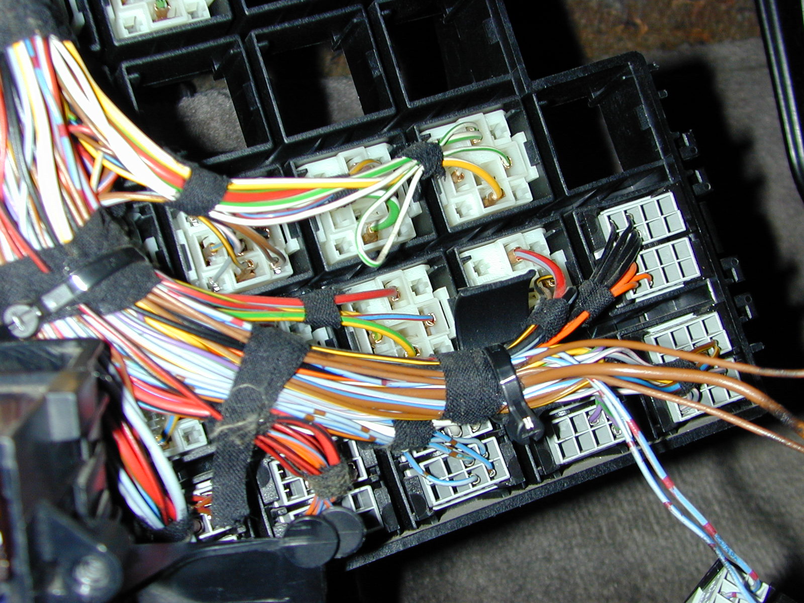
| Relay |
|---|
 | | |
| No. | Procedure | Instructions |
|---|
| 1 | Crimp on connectors | Crimp on the 999.650.321(0)?.22 Contact bushing to your GR wire running from the Driver Console Switch. |
| Access BS 15 | When viewed from the front, this is the third row down, first one from the left (indicated by -11-), bottom half (indicated by -15-). You will likely want to pull out the small gray divider from the back of the main relay housing to make it easier to work with. |
| 3 | Insert Connector | Insert your connector into opening 5 of the BS 15 slot (terminal 58d LED) of the relay panel divider. Replace the divider into the main housing. |
| 4 | Zip tie | Use small zip ties to attach your wire to the existing bundle. |
| Note: Open barrel (roll-over) connectors require the use of a unique crimp tool. I soldered mine as well. |
| Driver Seat Switch |
|---|
 | | |
| No. | Procedure | Instructions |
|---|
| 1 | Crimp connectors from seat | Crimp a 999.650.330.00 Electrical Connector (Female spades to tip switches) onto each of the three wires (YE/WT, YE/BK, YE/RD) that you ran from the Driver Seat. |
| 2 | Crimp connectors to GR/BL/RE wires | Combine the (GR/BL/RE) wire that you will run to the Passenger Console Switch and (GR/BL/RE) wire from the Bridge Plug/Relay and Crimp a single 999.650.330.00 Electrical Connector (Female spades to tip switches) on them. |
| 3 | Crimp connectors to passenger switch | Combine the (BR) wire that you will run to the Passenger Console Switch and (BR) wire from the Ground Point and Crimp a single 999.650.330.00 Electrical Connector (Female spades to tip switches) on them. |
| 4 | Insert into housing | Plug the connectors into corresponding numbered openings in the back of the 999.650.109.40 White Female Electrical Switch Connector Housing. Notice that there are tabs inside the connector housing which will hold the connectors in place. |
| 5 | Close retaining clips | Snap closed the retaining clips on the Switch Connector Housing. |
| 6 | Connect switch | Plug the 996.613.152.00.A02 Seat Heater Tip Switch into the connector housing. |
| Note: Open barrel (roll-over) connectors require the use of a unique crimp tool. I soldered mine as well. |
| Passenger Seat Switch |
|---|
 | | |
| No. | Procedure | Instructions |
|---|
| 1 | Crimp connectors from seat. | Crimp a 999.650.330.00 Electrical Connector (Female spades to tip switches) onto each of the three wires (YE/WT, YE/BK, YE/RD) that you ran from the Passenger Seat. |
| 2 | Crimp connectors from drivers switch | Crimp a 999.650.330.00 Electrical Connector (Female spades to tip switches) to each of the short wires (GR/BL/RE, BR) that you ran from the Drivers Console Switch |
| 3 | Insert into housing | Plug the connectors into corresponding numbered openings in the back of the 999.650.035.40 Black Female Electrical Switch Connector Housing. Notice that there are tabs inside the connector housing which will hold the connectors in place. |
| 4 | Close retaining clips | Snap closed the retaining clips on the Switch Connector Housing. |
| 5 | Connect switch | Plug the 996.613.152.00.A02 Seat Heater Tip Switch into the connector housing. |
| Note: Open barrel (roll-over) connectors require the use of a unique crimp tool. I soldered mine as well. |
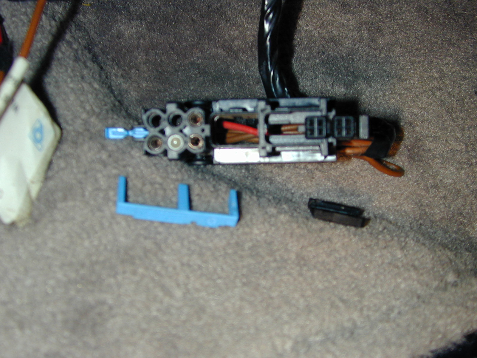
| Installing Pins in Central Plug (Car Harness) |
|---|
 | | |
| No. | Procedure | Instructions |
|---|
| 1 | Retaining clips | Pull out blue retaining clips and slide off black end-cap in order to access wire connector insertion points. |
| 2 | Solder connector | Audi 000-979-117 should be a yellow wire with connectors on both ends. Cut the Audi wire in half and solder one of the pieces to your RE/VI wire from fuse panel. Your RE/VI wire should now end in a female bullet connector. |
| 3 | Insert bullet connector | Insert RE/VI female bullet-style connector into the round -3- car harness opening as noted in the diagram. It should click and not pull out when fully inserted. |
| 4 | Solder Connectors | Audi 000-979-008-A should be a yellow wire with connectors on both ends. Cut the Audi wire in half and solder each of your YE/RD, YE/BK, YE/WT wires from seat switch to an Audi piece. Each of your YE/XX wires should now end with their own small square connector. |
| 5 | Insert square connectors | Insert the square connector with YE/RD, YE/BK, YE/WT, wires into the square openings on the car harness that are labeled B1-B3 as noted in the diagram. Take care to align the connectors so that they click into place and do not pull out. The retaining clips should help hold them in place. |
| 6 | Retaining clips | Reassemble car harness by reinserting blue retaining clips and sliding on black end-cap. |
| Note: You'll need to follow this procedure for both seats.. |
Connecting Seat Components
| Installing Pins in Central Plug (Main Seat Harness) |
|---|
 | | |
| No. | Procedure | Instructions |
|---|
| 1 | Pull slide | Pull slide -B- in -direction of arrow 1-. |
| 2 | Remove fuse | Lever out fuse -arrow 2- with a small screwdriver and remove completely. |
| 3 | Insert bullet connectors | Insert RE/VI and BR bullet-style connectors into the round -3- and -6- seat harness openings as noted in the diagram. They should click and not pull out when fully inserted. |
| 4 | Remove dummy insert | Remove the dummy insert from the main seat harness that is in place of the connector for pins B1-B4. |
| 5 | Insert square connector | Insert the square connector with YE/RD, YE/BK, YE/WT, BR wires from the heated seat harness into the square opening on the main seat harness that is labeled B1-B4 as noted in the diagram. An alignment flange should help you with the orientation. |
| 6 | Reinsert fuse | Reinsert fuse and push slide back together. |
| 7 | Main seat harness connection | Use plastic clip main seat wiring harness to afix it to existing hole in seat frame bottom |
| Note: You'll need to follow this procedure for both seats.. |
| Installing Control Module (996.618.521.00) and Seat Harness (996.612.540.01) |
|---|
 | | |
| No. | Procedure | Instructions |
|---|
| 1 | Backrest plug connection | Use plastic clip -6- from Wiring Harness Seat Heater to afix (RE/WT and RE/WT) plug connector to existing hole in seat frame bottom and connect plug -A- from backrest. |
| 2 | Seat cushion plug connection | Use plastic clip -6- from Wiring Harness Seat Heater to afix (RE/WT and BR) plug connector to existing hole in seat frame bottom and connect plug -B- from seat cushion. |
| 3 | Attach control module bracket | Slide 996.618.531.00 support control unit (metal bracket) -3- onto side of seat heating control module -2-. |
| 4 | Seat heating control module | Plug seat heating control module -2- into connection -C- from seat wiring harness. |
| 5 | Expanding rivet | Use expanding plastic rivet (999.591.712.40) -D-/-4- to attach bracket -3- (and thus control module) to existing hole in seat frame bottom. |
| Note: The control module for the seat is located on the right side for the driver's seat and on the left side for the passenger's seat. |
| Completed Seat |
|---|
 | Once your components are installed, the underneath of your seat should look like this. |
Test Continuity
Again, before proceeding, it's a good idea to test all of your wires at their connection points. This may seem tedious, but it's much easier to find and correct problems before you reattach the battery. No matter how careful you think you've been, there's always the possiblity of error.
You'll need to do a continuity test with a self-powered test lamp or an ohmmeter to tell if the two wire ends are connected to each other and uninterrupted. Be sure to make sure your test tool works before troubleshooting the wire.
Initial System Test
 Caution:Your Porsche is equipped with an electronic ignition system. When the ignition is on, high voltage is present in all wires connected with the ignition system; therefore, exercise extreme caution when working on any part of the engine while the ignition is on or the engine is running.
- Set your seats in the car, but don't bolt them in yet.
- Connect the car harness to the main seat harness. If all of your wiring is correct the colors from each side of the harness should align (e.g. YE/RE plugs into YE/RE). All of your connections should now be complete.
- Insert White 25A Fuse (999.607.060.00) into fuse slot SI A6.
- Connect the battery
- Put key in ignition and turn it to accessory mode
- Listen, look, and smell. If things seem out of sorts (popping sounds, smoke or sparks, burning smell), turn off the ignition and disconnect the battery immediately.
- Push the tip switches. You should be able to cycle through them displaying red, orange, and off.
- With the switches on, stick a tester prong into each of the RE/WT connectors for the seat coils (keep them connected). This will tell you if you're getting juice to seat coils. The signal to the coils is intermittent. So wait to see if you get a steady on-off-on signal to your test lamp.
- Test the BR lead, to check you ground, by putting an alligator clip on the ground bolt under the seat and the pronged lead to the brown connector for the seat coil.
- Sit in the seat. Keep in mind that it take a while for the coils to get heated. In addition, if your battery has been disconnected for a long period of time, you may not have much power left.
- Assuming that all has gone well, turn off the ignition, disconnect the battery, and remove the seats. Congratulations!
| Legend |
|---|
| GP | Ground point |
| SI A6 | Fuse seat heater left/right |
| BS 15 | Bridge Plug Relay |
| BL | Blue |
| BR | Brown |
| YE | Yellow |
| GN | Green |
| GR | Gray |
| PK | Pink |
| RE | Red |
| BK | Black |
| VI | Violet |
| WT | White |

